|
|
RVSM Training Booklet |
Chapter 1 |
|
Date 01.02.19 |
Cover Page |
Edn.1-rev.1 |
RVSM
TRAINING BOOKLET

0.1 List
of Abbreviations:
ACAS Airborne Collision Avoidance System
ACC Area Control Centre
ACH ATC Flight Plan Change Message
ACI Area of Common Interest
ACT Activation Message (OLDI)
ADEP Aerodrome of Departure
ADES Aerodrome of Destination
AFIL Flight Plan Filed in the Air
AFP ATC Flight Plan Proposal Message
AIC Aeronautical Information Circular
AIP Aeronautical Information Publication
AMC Airspace Management Cell
ANT Airspace and Navigation Team
APDSG ATM Procedures Development Sub-Group
APL ATC Flight Plan Message (IFPS)
ASE Altimetry System Error
ATC Air Traffic Control
ATM Air Traffic Management
ATS Air Traffic Service
CDB Central Data Base
CFL Cleared Flight Level
CFMU Central Flow Management Unit
CVSM Conventional Vertical Separation Minimum
EANPG European Air Navigation Planning Group
EATCHIP European Air Traffic Control
Harmonisation and Integration Program
ECAC European Civil Aviation Conference
FAA Federal Aviation Administration (USA)
FDPS Flight Data Processing System
FIR Flight Information Region
FL Flight Level
FLAS Flight Level Allocation Scheme
FMP Flow Management Position (ACC)
FPL Flight Plan
GAT General Air Traffic
GMU GPS Height Monitoring Unit
GPS Global Positioning System
HMU Height Monitoring Unit
ICAO International Civil Aviation Organization
IFPS Integrated Initial Flight Plan Processing System
IFPZ IFPS Zone
IFR Instrument Flight Rules
JAA Joint Aviation Authorities
JAA AMC JAA Acceptable Means of Compliance
JAR Joint Aviation Requirements
RFL Requested Flight Level
RGCSP Review of the General Concept of Separation Panel
RNAV Area Navigation
RNP Required Navigation Performance
RPL Repetitive Flight Plan
RTF Radiotelephony
RVSM Reduced Vertical Separation Minimum of 300 m /1 000 ft
Between FL 290 and FL 410 Inclusive
SARPs Standards and Recommended Practices
SDB State Data Base
SSEC Static Source Error Correction
SSR Secondary Surveillance Radar
STCA Short Term Conflict Alert
TA Traffic Advisory (ACAS)
TGL Temporary Guidance Leaflet (JAA)
TLS Target Level of Safety
TSA Temporary Segregated Area
TSE Total System Error
TVE Total Vertical Error
UAC Upper Area Control Centre
UIR Upper Flight Information Region
VFR Visual Flight Rules
VSM Vertical Separation Minimum
LoA Letter of Agreement
MASPS Minimum Aircraft System Performance Specification
MNPS Minimum Navigation Performance Specification
MTCD Medium Term Conflict Detection
NAT North Atlantic
NAT CMA North Atlantic Region Central
Monitoring Agency
NATSPG North Atlantic Systems Planning Group
NOTAM Notice to Airmen
OAT Operational Air Traffic
OLDI On-Line Data Interchange
RA Resolution Advisory (ACAS)
REJ Reject message (IFPS)
2. IMPLEMENTATION
OF RVSM
2.1 Background
In the late 1970s, faced with rising fuel costs and
growing demands for a more efficient use of the available airspace, the
International Civil Aviation Organization (ICAO) initiated a comprehensive
programme of studies to examine the feasibility of reducing the 2000 ft
Vertical Separation Minimum (VSM) applied above FL 290, to the 1000 ft VSM used
below FL 290. Throughout the 1980s, various studies were conducted, under the
auspices of ICAO, in Canada, Europe, Japan, and the USA.
The underlyning approach of the programmes was to:
·
determine the
height keeping accuracy of the altimetry systems of the then current aircraft
population;
·
establish the
causes of observed height keeping errors;
·
determine the
required safety levels for the implementation and use of a Reduced Vertical
Separation Minimum of 1000 ft at/above FL 290;
·
define a Minimum
Aircraft System Performance Specification (MASPS) - for aircraft altimetry and
associated height keeping equipment - which would improve height keeping
accuracy to a standard compatible with the agreed safety requirements for RVSM;
·
determine
whether the global implementation and use of RVSM was :
1.
technically
feasible, subject to the overriding need to satisfy the agreed safety
standards; and
2.
cost beneficial.
The results of these exhaustive studies demonstrated
that the global reduction of vertical separation was safe, feasible - without
the imposition of unduly demanding technical requirements, and cost beneficial.
The studies also showed that the types of aircraft and
the essentially unidirectional tidal flow of traffic in the North Atlantic
(NAT) Minimum Navigation Performance Specification (MNPS) airspace made this
Region an ideal candidate for the first implementation of RVSM.
Planning for RVSM in the NAT Region commenced in 1990.
The first stage of the Operational Evaluation phase, using the 1000 ft RVSM,
began on the 27th March 1997 at and between FL 330 and FL 370 inclusive. A
second stage will extend the use of RVSM to between FL 310 and FL 390
inclusive, in October 1998.
From the outset it was clear that the complex nature
of the European Air Traffic Services route structure, characterised by its wide
variety of aircraft types, high traffic density and the high percentage of
climbing and descending aircraft, would be a more demanding environment than
the NAT Region for the implementation of RVSM. Thus safety considerations were
given a high priority in the initial ECAC RVSM feasibility studies, which were
conducted under the auspices of the EUROCONTROL Airspace and Navigation Team
(ANT). These studies indicated that, subject to aircraft meeting the technical
requirements set out in the MASPS, RVSM could be introduced into the European
Region without prejudice to the required safety standards, and also that it
would provide a positive benefit to cost ratio over a wide range of assumptions
regarding future developments within the European aviation environment.
2.2 The
Need for RVSM
Over the last five years the improvements brought
about by the EUROCONTROL European Air Traffic Control Harmonisation and
Integration Program (EATCHIP) have contained the duration, and frequency of
occurrence, of ATC delays despite a yearly traffic increase of between 3 to
10%.
However current forecasts indicate that air traffic
movements will continue to rise, and will more than double by 2015 compared to
1996 figures. The anticipated trends are illustrated below:

It is accepted that major changes to the Air Traffic
Management (ATM) systems will be necessary in order to cope with this continued
traffic growth. Of the various measures under consideration, the application of
RVSM is considered to be the most cost-effective means of meeting this need.
RVSM will provide six additional flight levels for use
in the highly congested airspace between FL 290 to FL 410 inclusive, resulting
in the following benefits:
2.3 Optimum
Route Profiles
The availability of the additional flight levels in
this altitude band will allow Operators to plan for, and operate at or closer
to, the optimum vertical route profile for the particular aircraft type. This
will provide fuel economies in terms of both the fuel carried, and the fuel
burn, for the flight. The economies are estimated at between 0.5% and 1% of the
total fuel burn.
2.4 Increased
ATC Capacity
A series of ATC Real Time Simulations carried out at
the EUROCONTROL Experimental Centre (EEC) at Bretigny have provided evidence
that RVSM can reduce controller workload. With the same sectorisation and
traffic flow, controller workload in an RVSM environment would not reach
today's levels until an increase in traffic growth of around 20% had been
experienced. There is also potential for further growth, through a revised
airspace structure including, for example, the introduction of additional
sectors.
The presence of non-RVSM approved State aircraft
flying along the route network is likely to decrease the expected capacity
gains.
2.5 Cost
Benefit Assessment
A Cost Benefit Assessment (CBA) of the implementation
of RVSM in the European RVSM Area was conducted by first establishing a
"do nothing" baseline whereby only the capacity gains derived from
existing approved EATCHIP Programs are achieved. In this situation the
anticipated traffic growth would ultimately exceed capacity and delays and
congestion, and the consequent financial penalties would become increasingly
severe over time. The additional capacity, which will result from the
implementation of RVSM, could significantly reduce these delays and hence
generate large benefits.
Assumptions regarding the anticipated traffic growth
rates used in the CBA varied from 1.9% (Low) to 3.1% (Medium) to 3.8 % (High).
The use of midrange values indicated that the implementation of RVSM would
provide a Benefit to Cost ratio of 11:1 over the period 1997 to 2016. As
current European traffic growth rates are at the high end of the above range,
and are expected to remain so over the next decade, there is every expectation
that the quoted benefit to cost ratio can be achieved.
3. RVSM
- System Safety Standards
The safety standards appropriate to operations in an
European RVSM environment have been derived from those developed by the ICAO
Review of the General Concept of Separation Panel (RGCSP) in which the agreed
tolerable level of risk is defined as a Target Level of Safety (TLS) which is
expressed in terms of fatal accidents per aircraft flight hour. Based upon TLS
values derived in the 1970s in the establishment of route spacing, and taking
into account the subsequent increases in traffic, the RGCSP adopted a TLS of
2.5 x 10⁻⁹ fatal accidents per aircraft flight hour as a consequence of
technical (altimetry) errors, for the implementation of RVSM. This TLS was used
as the basis of the development of the Global RVSM MASPS.
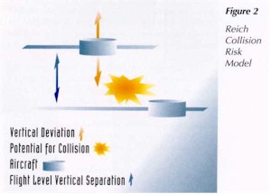
In determining whether or not the proposed operations
in RVSM airspace can meet the TLS, it is necessary to estimate the risk of a
collision, in the vertical plane, in that environment. This is done by
modelling the operational characteristics of the particular airspace together
with the navigation performance and the physical dimensions associated with the
expected aircraft population.
This is based on the Reich Collision Risk Model (CRM)
shown diagramatically in figure 2. The output provides an estimate of the level
of risk of a mid-air collision as a consequence of a failure of some element of
the airspace system. In the RVSM case, the failure would be the loss of
vertical separation as a result of a technical error. The key parameters in the
modelling of RVSM operations are:
·
the height
keeping accuracy of the aircraft population;
·
the aircraft
passing frequency - which is a means of quantifying the traffic density of the
given airspace;
·
the lateral
track keeping accuracy of the aircraft population.
Note 1: As track keeping accuracy improves, the risk of collision in the
vertical plane between aircraft following the same track increases, and this
places increased demands upon the vertical performance.
Note 2: In the European Region, a modified version of the Reich CRM will be
used. This will combine the passing frequency and track keeping accuracy
parameters into a
"Lateral Plan Overlaps per Aircraft Flight Hour
"parameter. This is necessary because of the amount of crossing traffic
experienced in Europe.
In the planning for RVSM operations in the NAT Region,
the North Atlantic Systems Planning Group (NATSPG) adopted the RGCSP
recommendations but also decided to increase the scope of the TLS to include an
allowance for the risk of a mid-air collision as a consequence of a height
deviation caused by "operational errors". Thus a further risk budget
of 2.5 x 10⁻⁹ fatal accidents per aircraft flight hour was added to give an
overall TLS of 5 x 10⁻⁹ fatal acci dents per aircraft flight hour relating to
all possible causes of height deviation.The overall TLS, and the underlying
philosophy was approved by the ANT for application in the European RVSM
Airspace.
The assessment of the system safety confirmed that,
taking due account of the expected growth of traffic in the European Airspace,
a 300m (1000 ft) VSM was technically feasible, subject to:
·
the mandatory
carriage of the altimetry and height keeping systems, which comply with the
MASPS, by all aircraft operating in the RVSM airspace;
·
new operational
procedures; and
·
the
establishment of a comprehensive means of monitoring the safe operation of the
system.
3.1 RVSM
- Implementation Programme
The Program consists of a series of coordinated
activities, performed within the EUROCONTROL Agency, ICAO, JAA, Participating
States and User Organisations.

To-date the program has followed the general strategy
set out in the ICAO Doc. 9574 - Manual on the Implementation of RVSM, which
proposed a multi-step approach within four distinct phases:
Phase 1: Initial Planning
·
Step 1:
Assessment of System Safety
·
Step 2:
Assessment of Costs and Benefits from RVSM
·
Step 3:
Elaboration of program plans and production of technical specifications
This phase was completed in June 1997. The EATCHIP
Project Board reviewed the progress made on the RVSM Program and recommended
that work should continue so that full implementation can be achieved on the
target date of November 2001.
This phase was completed by the endorsement of the
program by the ICAO European Air Navigation Planning Group (EANPG) in December
1997.
Phase 2: Advanced
Planning and Preparation
In this phase the emphasis of the work program will
move from the theory and initial design of the total system to the practical
application and introduction of the system requirements.
The objectives of this phase are:
·
Step 1: to
commence the preparation of the ATS environment for RVSM operations.
·
Step 2: to
prepare the aircraft for RVSM operations.
·
Step 3: to
prepare a monitoring environment to allow confirmation of the technical
performance of aircraft.
Steps 2 and 3 above will allow Phase 3 to start. Step
1 above has to be complete before RVSM (Phase 4) can be implemented.
Phase 3:
Verification of Aircraft Performance
The purpose of the Verification Phase is to confirm,
in a 2000 ft vertical separation environment:
·
the
effectiveness of the RVSM approval process;
·
the efficacy of
the MASPS, by measuring the height keeping performance accuracy of the maximum
possible number of aircraft which have obtained RVSM airworthiness approval;
·
that the safety
levels of the proposed 1000 ft RVSM system will remain at, or better than, that
established by the TLS.
This phase will continue until all aspects of the work
program necessary to the successful completion of the verification process, and
to the introduction of RVSM, have been completed. This is expected to take
approximately one year.
Phase 4:
Introduction of RVSM
The introduction of RVSM does not mark the
end to the Program. This phase will be used to confirm that:
·
all elements of
the total system are operating satisfactorily, and
·
the level of
"vertical" risk in the system is below that tolerated by the TLS.
This phase will support the resolution of any
operational issues, which might be revealed following the implementation of
1,000 ft VSM.
Phase 4 will continue until it is possible to confirm
that the long-term safety of 1,000 ft VSM can be assured without further
monitoring.
Figure 3 is the presently proposed timetable for the
introduction of RVSM. The ability to meet this timescale depends on all
stakeholders being able to complete the tasks for which they are responsible in
sufficient time.
3.2 Key
Elements of the RVSM Program
This section provides a summary of the key elements of
the future work program to implement RVSM in the airspace of the European
Member States and other Participating States
3.2.1 Aircraft Requirements
3.2.1.1 Approval For RVSM Operations
To operate in the notified European RVSM Airspace,
both the Operator and the aircraft will need to be RVSM approved. This approval
consists of:
1.
RVSM
Airworthiness Approval. This is the approval granted by the State Authority to
indicate that an aircraft has been modified and/or inspected in compliance with
the applicable approval criteria (eg. Service Bulletin, Supplemental Type
Certificate), and is therefore eligible for monitoring as part of the
Verification Phase.
2.
RVSM Operational
Approval. This is the approval granted by the State Authority to the Operator
to indicate that:
·
the aircraft
holds RVSM airworthiness approval;
·
the operating
procedures and continued air worthiness procedures (maintenance and repair
procedures) are acceptable; and,
·
the approval of
an Operations Manual, where required.
Approval criteria for RVSM Operations will
be stated in JAA Temporary Guidance Leaflet No. 6 (due to be published in
spring 1998). The basic technical criteria of this leaflet will be identical to
that previously published in JAA Information Leaflet No. 23, which it replaces,
and will be the JAA MASPS for RVSM.
3.2.1.2 Airspace and ATC Requirements
3.2.1.2.1 Airspace Organization
Work is in progress to define the airspace
requirements for RVSM operations. These requirements can be divided into three
distinct but overlapping packages:
·
The definition
of the continuous area of RVSM applicability.
Note: ICAO have urged non-ECAC States
with an operational interface with the ECAC area, in particular those which
would make the RVSM area an operationally coherent and acceptable airspace, to
work closely with ECAC States to introduce RVSM within the same timescales
through active participation in related RVSM activities.
·
The evaluation
of the impact of RVSM on the Route Network and the adaptation, as required, of
the Route Network and associated Flight Level Allocation System.
·
The adaptation,
as required, of the airspace structure and ATC sectors.
3.2.1.2.2 ATC Procedures
The development of ATC Operational Procedures for the
European RVSM airspace is being finalised. The main areas of work are:
·
Flight Planning
Procedures
·
Contingency
Procedures
·
Transition
Procedures
·
Procedures for
handling non-RVSM approved State aircraft
These procedures, once endorsed, will be the basis for
the development of an RVSM Operations Manual and ATC Training Syllabi to
support RVSM.
3.2.1.2.2 ATC System Support Facilities
Two items have been assessed as having significant
safety implications:
·
To permit
operations by non-RVSM approved State aircraft, ATC will be obliged to apply
two distinct vertical separation minima within RVSM airspace.
·
ATC will need to
ensure that non-RVSM approved aircraft, other than State aircraft, are not
cleared into the RVSM airspace.
An accurate, timely and unambiguous display of
information to the controller will be necessary to ensure the safe handling of
this mix of aircraft in the RVSM airspace. The safe application of RVSM will
require procedures for handling non-RVSM approved State aircraft. Operation of
these procedures requires the provision of specialised ATC system support tools
which:
·
ensure that ATC
can readily identify the non-RVSM approved State aircraft and can apply 2000 ft
vertical separation from other aircraft; and
·
prevent
increased controller workload created by the handling of non-RVSM approved
State aircraft.
Dependent upon the nature of the sector, the means of
meeting these requirements could include the modification of the controller’s
display. This requirement could be one of the critical tasks of the program.
|
|
3.2.2 Monitoring Requirements
A prerequisite for the implementation of RVSM is the
monitoring of the overall system performance to ensure that the system safety
targets are:
·
achieved -
during the Verification phase; and
·
maintained -
once full implementation has been introduced.
The monitoring process is based upon the application
of the principles of the traditional Reich Collision Risk Model which employs
data inputs on airspace and aircraft parameters in order to model operations in
the particular airspace. The most important of these parameters, and the most
difficult and costly to acquire, is an accurate measurement of the height
keeping performance of the aircraft population.
Currently there are two accepted methods of obtaining
the necessary data.
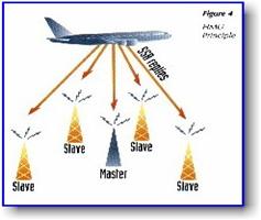
·
Height
Monitoring Unit (HMU). This is a fixed ground based system which employs a
network of a Master and 4 Slave Stations to receive aircraft SSR Mode A/C
signals to establish the three dimensional position of the aircraft. The
geometric height of the aircraft is measured to an accuracy of 50 ft (1
Standard Deviation (SD)). This is compared, in near real time, with
meteorological input data on the geometric height of the assigned Flight
(Pressure) Level to obtain a measurement of the Total Vertical Error (TVE) of
the target aircraft. The aircraft SSR Mode C data is also recorded to determine
the extent of any Assigned Altitude Deviation (AAD) and for subsequent aircraft
identification, when the SSR Mode S response is not available.
·
GPS Monitoring
Unit (GMU). A GMU is a portable "box" (contained in a carry case
approximately 45 x 40 x 30 cm3) which contains a GPS receiver and a device for
storing the GPS three dimensional position data, and two separate GPS receiver
antenna's which need to be attached to aircraft windows using suction pads. The
GMU is positioned on board the candidate aircraft and, being battery powered,
functions independently of the aircraft systems. Following the flight, the
recorded GPS data are sent back to a central site where, using differential
post processing, aircraft geometric height is determined.
It is intended that the European Monitoring System
should be a hybrid system of HMUs and GMUs, which makes optimum use of the
advantages offered, by each system. Thus the strategic characteristics of the
HMU - providing a predictable rate of collection of high quality data with
relatively high installation and low maintenance/ongoing operating costs - can be
blended with the tactical flexibility of the GMU which permits the targeting of
specific aircraft at a low initial purchase price, and relatively high
operating costs in both manpower and logistics.

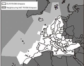
It is planned that there should be four European HMUs
(three new facilities plus the Strumble HMU, which was sited for the monitoring
of the NAT traffic). The new HMUs have been positioned so as to obtain the
maximum number of measurements of aircraft operating on their normal routes, as
shown in figure 5. The primary means of monitoring the aircraft of those
operators whose routes do not pass near to an HMU, will be a GMU. In some cases
it may be necessary to request an Operator to make a minor deviation from the
normal route in order to overfly an HMU. Routing an aircraft over an HMU during
a non-revenue flight (eg. maintenance) is another alternative.
All data from the HMUs and GMUs will be collected and
processed at a designated Monitoring Cell. The anticipated functions of the
Cell will include:
·
maintaining a
data base of aircraft approvals and measured height keeping performance;
·
analysis of
height keeping performance data to:
1.
initiate
appropriate follow up action with the Operator of any aircraft having a large
height keeping error (eg. more than 300 ft); and
2.
attempt to
establish the cause of any large deviations.
·
execution of
such measures as necessary to confirm that action has been taken to correct the
cause of the deviation;
·
assessment and
evaluation of the risk of collision (in the vertical plane) in the RVSM
airspace;
·
provision of
periodic reports on the safety of the system to the designated authority.
3.3 Action Necessary to Support the
Successful implementation of RVSM
3.3.1 Action by State Authorities whose aircraft fly into the RVSM
Area:
·
To meet the
proposed timetable, States should take such action as necessary to require that
all non-State aircraft, which will operate in the European RVSM area, obtain
the appropriate RVSM airworthiness approval by mid 2000 and be approved for
RVSM operations by the third quarter of 2001.
·
Following the
publication of the JAA TGL No. 6, State Airworthiness Authorities should make
available the necessary resources and documentation to publicise and facilitate
the process whereby Operators can obtain airworthiness and operational approval
for RVSM operations.
·
To complete the
many tasks listed earlier, it is essential that the aviation authorities of all
ECAC Member States and other Participating States are fully involved in, and
commit a high level of support to:
1.
the consultative
and decision making processes;
2.
the planning and
provision of the ATC and monitoring infrastructure required to support RVSM
operations, specifically within their area of responsibility and generally
throughout the European area; of particular importance is the provision of the
necessary ATC support tools and facilities to allow RVSM to be introduced in
November 2001;
3.
the siting,
provision and operation of the monitoring facilities by those states hosting
the HMUs.
3.3.2 Action
by Airlines
Airlines who intend to operate their aircraft in the
future European RVSM airspace should:
·
take such action
as necessary to obtain appropriate RVSM approvals from the appropriate State
Authority before aircraft performance verification commences. This is essential
to the successful completion of the Verification Phase and to the timely
implementation of RVSM;
·
co-operate, to
the maximum extent possible, in ensuring that their aircraft are routed over an
HMU, or are measured by a GMU, during the Verification Phase;
·
co-ordinate with
Manufacturers to prepare, and make available, RVSM airworthiness approval
packages.
4. RVSM OPERATION MANUAL
FLIGHT CREW PROCEDURES
4.1 Introduction
Flight crews will need to have an awareness of the
criteria for operating in RVSM airspace and be trained accordingly. The items
should be standardised and incorporated into training programs and operating
practices and procedures. Certain items may already be adequately standardised
in existing procedures. New technology may also remove the need for certain
actions required of the flight crew. If this is so, then the intent of this
manual can be considered to be met.
Note: This document is written for Airlines who uses RVSM
airspace, and as such is designed to present all required actions.
4.2 General
Reduced Vertical Separation Minimum in the EUR RVSM
Airspace will permit the application of a 1000 ft vertical separation minimum
between suitably equipped aircraft in the level band FL290-FL410 (inclusive) on
24/01/02.
The purpose of RVSM is to increase airspace capacity
and provide airspace users with more flight levels and thus optimised flight
profiles.
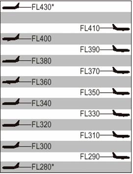
EURO
RVSM AREA RVSM
CRUISING FLIGHT LEVELS
* Non RVSM levels
4.3 Approval
for RVSM Operations
Only RVSM approved aircraft will be permitted to
operate within the EUR RVSM
Airspace. The approval is issued to aircraft operators
by the responsible authority once an operator has achieved the following:
·
each aircraft
type has received airworthiness approval demonstrating compliance with the RVSM
Minimum Aircraft System Performance Specification (MASPS),
·
the State's
approval of both the operations manual and the maintenance procedures specific to RVSM operations.
4.4 Non-RVSM
Approved State Aircraft
State aircraft are exempted from having to meet the
RVSM MASPS. As a consequence, State aircraft can be accommodated in the EUR
RVSM airspace provided that ATC maintains a minimum vertical separation of 2000
ft between such aircraft and all other IFR aircraft. In Field 18 of the ICAO
FPL, State aircraft shall then request special handling by filling “
STS/NONRVSM” .
4.5 Height
Monitoring Principles
Comprehensive means of monitoring the height-keeping
performance of aircraft in the EUR RVSM Airspace has been developed utilising
two types of monitoring equipment:
Height Monitoring Units (HMUs) - fixed ground based height-monitoring facilities at Linz,
Nattenheim & Geneva which monitor passing aircraft normally without action
from aircraft operators;
GPS Monitoring Units (GMUs) - portable monitoring units carried on board aircraft to
supplement HMUs & monitor aircraft which are not normally flying over HMUs
RVSM compliant aircraft are required to participate in
the monitoring program which will commence in Spring 2000. In some cases,
aircraft may request a re-routing so that they may be height monitored.
4.6 RVSM
Procedures in Transition Areas
A number of FIR/UIRs in the EUR RVSM Airspace have
been designated to handle the transition of aircraft from an RVSM to a non-RVSM
environment and vice-versa. Within this “EUR RVSM Transition Airspace”, special
procedures will allow ATC to transition both RVSM and non-RVSM Civil and State
aircraft. Flight crews may expect to change from Conventional Flight Levels to
RVSM Flight Levels and vice- versa. ATC will continue to provide a 2,000 feet
VSM between a non-RVSM approved aircraft and any other aircraft.
4.7 Aircraft
Equipment
The minimum equipment list (MEL) fulfilling the MASPS
consists of :
1. Two independent altitude
measurement systems each equipped with:
·
cross-coupled
static/source system with ice protection if located in areas subject to ice
accretion,
·
display of the
computed pressure altitude to the flight crew,
·
digital encoding
of the displayed altitude
·
signals
referenced to a pilot selected altitude for automatic altitude control and
alerting,
·
Static source
error correction.
2. One SSR transponder with an
altitude reporting system in use for altitude keeping.
3. An altitude alerting system.
4. An automatic altitude control
system.
4.8 Contingency
Procedures
1.
the pilot shall notify ATC of any contingency
(equipmentfailure, weather hazards such as severe turbulence etc…) which affect
the ability to maintain the cleared level or the RVSM requirements (eg. MEL).
2.
ATC may take appropriate tactical actions to
ensure that safe separation is maintained, including reversion to a 2000ft
separation minimum
3.
when notified by ATC of an assigned altitude
deviation of more than 300 ft (90 m), the pilot shall take action to return to
the cleared level as quickly as possible.
4.
If unable to notify ATC, the pilot shall follow
established contingency procedures and obtain ATC clearance ASAP.
5.
Examples
of equipment failures which should be notified to ATC are:
·
failure of all
automatic altitude-control systems aboard the aircraft;
·
loss of redundancy of altimetry systems;
·
loss of thrust on an engine necessitating
descent; or
·
any other equipment failure affecting the
ability to maintain cleared flight level;
The pilot should notify ATC when encountering greater
than moderate turbulence. If unable to notify ATC and obtain an ATC clearance
prior to deviating from the cleared flight level, the pilot should follow any
established contingency procedures and obtain ATC clearance as soon as
possible.
4.9 ACAS
TCAS Version 6.04A is designed for a non-RVSM
environment. ACAS II (TCAS Version 7.0) has improved compatibility with RVSM.
The Mandatory Carriage and Operation of ACAS II for aircraft above 15000 kgs
and more than 30 passengers started on 1 January 2000 with a transition period
ending in March 2001.
4.10 Flight
Planning
Flight crews shall verify:
·
the condition of
the equipment required for RVSM operations and that maintenance actions have
been taken to correct defects,
·
the condition of
static sources,
·
the altimetry
accuracy by setting the QNH or the QFE. The reading should then agree with the
altitude of the apron or the zero height indication within a 75ft (23m)
tolerance.
4.11 Pre-Flight
Procedures
The following actions should be accomplished during
the pre-flight procedure:
·
review technical
logs and forms to determine the condition of equipment required for flight in
the RVSM airspace. Ensure that maintenance action has been taken to correct
defects to required equipment;
·
during the
external inspection of aircraft, particular attention should be paid to the
condition of static sources and the condition of the fuselage skin near each
static source and any other component that affects altimetry system accuracy.
This check may be accomplished by a qualified and authorised person other than
the pilot (e.g. a ground engineer);
·
before takeoff,
the aircraft altimeters should be set to the QNH of the airfield and should
display a known altitude, within the limits specified in the aircraft operating
manuals. The two primary altimeters should also agree within limits specified
by the aircraft operating manual. An alternative procedure using QFE may also
be used. Any required functioning checks of altitude indicating systems should
be performed.
Note. The
maximum value for these checks should not exceed 23m (75ft).
·
Before take-off,
equipment required for flight in RVSM airspace should be operative, and any
indications of malfunction should be resolved.
The flight crew shall pay particular attention to
conditions that may affect operation in RVSM airspace:
·
verifying that
the aircraft is RVSM approved, ie compliant with the MEL
·
analysing the
reported and forecast weather that may affect RVSM requirements (turbulence,
icing …),
·
reviewing the
manufacturer's and the operator's restrictions concerning RVSM operations.
·
ICAO FPL : the
letter W shall be inserted in Field 10 if RVSM approved
·
RPL : the letter
W shall be inserted in Item EQPT/ if RVSM approved, regardless of the requested
FL.
4.12 Procedures
Prior To RVSM Airspace Entry
The following equipment should be operating normally
at entry into RVSM airspace:
·
Two primary
altitude measurement systems.
·
One automatic
altitude-control system.
·
One
altitude-alerting device.
Note:
Dual equipment requirements
for altitude-control systems will be established by regional agreement after an
evaluation of criteria such as mean time between failures, length of flight
segments and availability of direct pilot-controller communications and radar surveillance.
·
Operating
Transponder. An operating transponder may not be required for entry into all
designated RVSM airspace. The operator should determine the requirement for an
operational transponder in each RVSM area where operations are intended. The operator
should also determine the transponder requirements for transition areas next to
RVSM airspace.
Note: Should any of the required
equipment fail prior to the aircraft entering RVSM airspace, the pilot should
request a new clearance to avoid entering this airspace;
4.13 In-Flight
Procedures
·
all the required
equipment shall be monitored to ensure satisfactory operation before and within
RVSM airspace.
·
when changing
levels, the aircraft should not overshoot or undershoot the cleared flight
level by more than 150 ft (45 m).
·
the automatic
altitude control system shall be engaged during level cruise by reference to
one of the two altimeters. If fitted, the altitude capture feature shall be
used whenever possible for the level off
·
cross checks of
the primary altimeters shall be made at intervals of approximately one hour.
These primary altimeters shall agree within 200’(60m).
The following practices should be incorporated into
flight crew training and procedures:
·
Flight crews
will need to comply with any aircraft operating restrictions, if required for
the specific aircraft group, e.g. limits on indicated Mach number, given in the
RVSM airworthiness approval.
·
Emphasis should
be placed on promptly setting the sub-scale on all primary and standby
altimeters to 1013.2 (hPa) /29.92 in.Hg when passing the transition altitude,
and rechecking for proper altimeter setting when reaching the initial cleared
flight level;
·
In level cruise
it is essential that the aircraft is flown at the cleared flight level. This
requires that particular care is taken to ensure that ATC clearances are fully
understood and followed. The aircraft should not intentionally depart from
cleared flight level without a positive clearance from ATC unless the crew are
conducting contingency or emergency manoeuvres;
·
When changing
levels, the aircraft should not be allowed to overshoot or undershoot the
cleared flight level by more than 45 m (150 ft);
Note: It is recommended that the level off be accomplished using the altitude
capture feature of the automatic altitude-control system, if installed.
·
An automatic
altitude-control system should be operative and engaged during level cruise,
except when circumstances such as the need to re-trim the aircraft or
turbulence require disengagement. In any event, adherence to cruise altitude
should be done by reference to one of the two primary altimeters. Following
loss of the automatic height keeping function, any consequential restrictions
will need to be observed.
·
Ensure that the
altitude-alerting system is operative;
·
At intervals of
approximately one hour, cross-checks between the primary altimeters should be
made. A minimum of two will need to agree within ±60 m (±200 ft). Failure to
meet this condition will require that the altimetry system be reported as
defective and notified to ATC;
·
The usual scan
of flight deck instruments should suffice for altimeter cross-checking on most
flights.
·
Before entering
RVSM airspace, the initial altimeter cross check of primary and standby
altimeters should be recorded
Note: Some systems may make use of automatic altimeter comparators.
·
In normal
operations, the altimetry system being used to control the aircraft should be
selected for the input to the altitude reporting transponder transmitting
information to ATC.
·
If the pilot is
advised in real time that the aircraft has been identified by a
height-monitoring system as exhibiting a TVE greater than ±90 m (±300 ft)
and/or an ASE greater than ±75 m (±245 ft) then the pilot should follow
established regional procedures to protect the safe operation of the aircraft.
This assumes that the monitoring system will identify the TVE or ASE within the
set limits for accuracy.
·
If the pilot is
notified by ATC of an assigned altitude deviation which exceeds ±90 m (±300 ft)
then the pilot should take action to return to cleared flight level as quickly
as possible.
4.14 Post
Flight
·
In making
technical log entries against malfunctions in height keeping systems, the pilot
should provide sufficient detail to enable maintenance to effectively
troubleshoot and repair the system. The pilot should detail the actual defect
and the crew action taken to try to isolate and rectify the fault.
The following information should be recorded when
appropriate:
·
Primary and
standby altimeter readings.
·
Altitude
selector setting.
·
Subscale setting
on altimeter.
·
Autopilot used
to control the aeroplane and any differences when an alternative autopilot
system was selected.
·
Differences in
altimeter readings, if alternate static ports selected.
·
Use of air data
computer selector for fault diagnosis procedure.
·
The transponder
selected to provide altitude information to ATC and any difference noted when
an alternative transponder was selected.
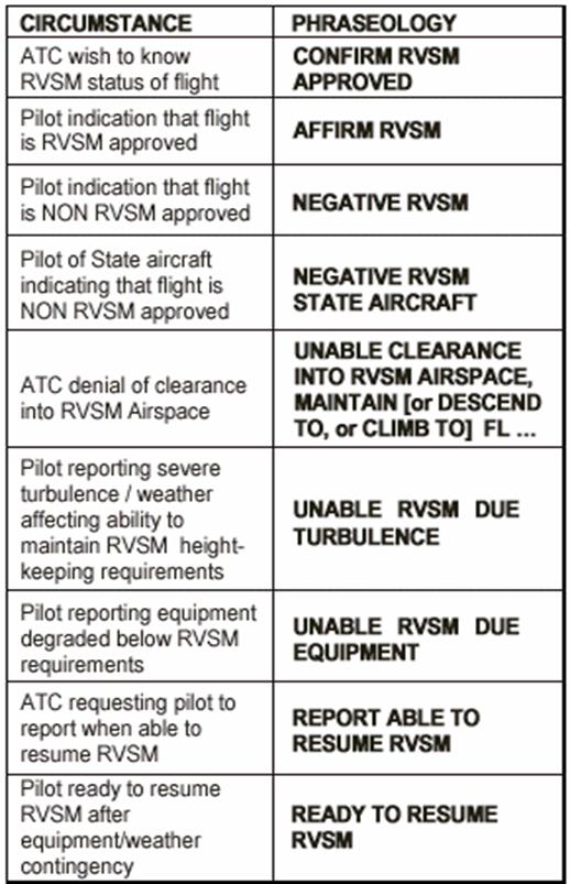
5. PHRASEOLOGY
RVSM Booklet Date
01.02.19sb Page
22 of 22